topamax once a day

Raspberry Pi + PWM RGB LED Strip

This tutorial demonstrates how to easily use a Raspberry Pi to drive 12V RGB LED strips using Pulse Width Modulation (PWM).  Out of the box, the Raspberry Pi has only one GPIO pin that is capable of pulse width modulation (PWM).  However, thanks to the efforts of Richard Hirst and his servoblaster kernel module, standard GPIO pins can be used to perform PWM.

Note: The flashing of the LED strip due to PWM is only noticeable in the uploaded video; in reality, the colors progress smoothly without any visible flashing.

Hardware

Parts needed:

  • Raspberry Pi
  • 3 x TIP120 power transistors
  • RGB LED strip
  • Perfboard/Breadboard
  • Hook-up wire


Assembly


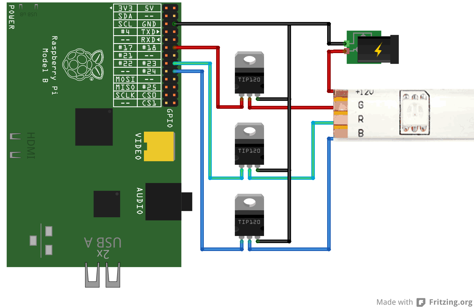
Connect a 12V power supply to the 12V pad on the RGB LED strip, connect the base of each TIP120 power transistor to its respective GPIO pin (pins 18, 23, and 24 in this example), connect the collector of each to its matching pad on the LED strip, and finally, connect the emitters to common ground for both the Raspberry Pi and the 12V power supply. Here is a diagram of the circuit  (created with Fritzing):

raspi_rgb_led


Software

Configure servoblaster.

The next step is to configure the servoblaster kernel driver. The driver creates a device file, /dev/servoblaster to which commands can be sent to control the servos. The commands take the form “=” with servo number representing the desired servo (0-7 in this case) and servo position representing the pulse width in units of 10 µs. For example, to send servo 3 a pulse width of 120 µs:

echo 3=120 > /dev/servoblaster

To setup the servo blaster on the Raspberry Pi, we will need to have git installed to pull down the sources. If you don’t have it installed already, open a terminal and run:

sudo apt-get install git-core

Then pull down the sources from Richard’s Github repo:

git clone https://github.com/richardghirst/PiBits.git

Now change into the servo blaster directory:

cd PiBits/ServoBlaster

And compile and install the module:

make install_autostart

This command also sets up the necessary udev rules for accessing the /dev/servoblaster device. Note: using the ’install_autostart ’ command will set up a raspberry pi to load the servo blaster kernel module on every boot. If you don’t want this behavior, execute ‘make install’ instead. In either case, the module will not yet be loaded so go ahead and install it using modprobe:

sudo modprobe servoblaster


Sample code usage.

Now that all the prerequisites have been installed and the servo blaster device configured, on to the actual sample code. The python sample script uses PWM to fade from blue to violet, to red, to yellow, to green, to teal, back to blue.


  • deltablue

    Thank you for the very interesting tutorial!

    One stupid question from a total noob: Do I read the python-code correctly that you write to all 8 GPIO-pins? It is not possible to adress only the three pins used (18,23,24 in your example)?

    Thank you!

  • Pingback: Raspberry Pi + PWM RGB LED Strip #piday #raspberrypi @Raspberry_Pi « adafruit industries blog()

  • sebf60

    Thank you too for this tutorial,

    Another stupid question from another noob:
    What is the max current which can passthrough the TIP120 ?
    how much voltage the pwm signal use on the PI ? 1v , 3 ?

    For exemple I know that the arduino has 5V pmw output.

    Regards,

  • sarfata

    Hi Michael,

    Thanks for sharing this interesting experiment. I just tried doing it “at home” but it seems that the ServoBlaster module will only let me send a pulse that’s 1/8th of the total PWM cycle. So the PWM value is between 0% and 12.5% which kind of sucks …

    How did you get around that?

  • Richard Hirst

    Hi,
    I wrote ServoBlaster. Servoblaster currently only lets you have one output on at a time, in an attempt to limit the maximum current requirements of multiple servos, and to avoid spikes when you suddenly turn on 8 outputs.

    If you want to hack, I’d start with the new userspace daemon (servod) rather than the kernel base servoBlaster.ko. The user space one basically has an array of words that it writes to the gpio control registers one per 10us. You could change it to start all pulses at the start of the 20ms cycle, and then turn each off at whatever point you wanted, right up to the end of the 20ms cycle. Not so easy with the kernel space implementation.

    There is also http://www.raspberrypi.org/phpBB3/viewtopic.php?f=37&t=22923 but I don’t think it is open source, and it is for C coders (and I’ve not tried to use it myself).

  • I keep getting this error on the last step..

    ERROR: could not insert ‘servoblaster’: Exec format error

    any ideas?

    • sarfata

      Yes, your kernel probably does not match the one that was used to build the module.

      You should use the daemon (servod). Note that you will still only get 12.5% pwm at most. I am working on this right now and will be sharing a solution very soon.

  • sarfata

    Hi,

    I have created a new daemon based on Richard’s code that you can use to generate PWM for any pulse length.

    It is available on github:
    https://github.com/sarfata/pi-blaster

    And I have used it to drive high power led:
    http://www.tbideas.com/blog/2013/02/controling-a-high-power-rgb-led-with-a-raspberry-pi/

    Feedbacks most welcomed!

  • Hi Michael, thanks for your excellent and simple writeup!

    I’m getting everything to work just fine, however I am definitely getting a visible flicker on almost all colors, looking like it’s around 20-25Hz or so. Is this something that can be eliminated? In your write up, you wrote “in reality, the colors progress smoothly without any visible flashing.”

    Thanks!

  • aldopwn

    How can I make a led strip fade from 0% brightness to 100% brightness. The sample code doesn’t help me very much.

    • If you have a look at my sample code over here:
      http://elfboimakingstuff.tumblr.com/post/132956410578/raspberry-pi-pwm-rgb-led-strip

      You’ll notice two functions, pwm and setledcolour. In this crude first script, setledcolour uses the global gamma variable instead of a parameter, you should change that if you want to use gamma correction. Also, this is Python 2, I’m going to rewrite this for Python 3 soon.

      My code was written for pi-blaster instead of servoblaster, and you should be using pi-blaster, too. since servoblaster will always flicker.

      Now, if you want to increase the brightness without changing colour, you need a different colour system. The colorsys module has all the things you need for that:
      https://docs.python.org/2/library/colorsys.html

      If you store your colour as HSV instead of RGB, you can change the hue, saturation, and lightness, so you could just make a for loop, increasing the V from 0.0 to 1.0, while keeping H and S constant, use colorsys.hsv_to_rgb for conversion, and use those values to call setledcolour.

  • Pingback: Lighting up a workspace twofer()

  • Pingback: Lighting up a workspace twofer | Daily IT News on IT BlogIT Blog()

  • Pingback: Lighting up a workspace twofer | Make, Electronics projects, electronic Circuits, DIY projects, Microcontroller Projects - makeelectronic.com()

  • Pingback: Lighting up a workspace twofer | ledfreaks.net()

  • Sebastian

    Nice work! One question; does this also work with a 24v led strip with a 24v power supply or will that fry your Pi?

  • Kai

    I have a question.
    I need heatsinks for transistors?
    Because there are two different types of transistors.

    Sorry, my English is very bad 😀

  • guilherme lourenço

    how can I turn this tape programs Boblight or use the ambilight version xbian

  • leffe

    Hi!
    Very nice tutorial.

    What rgb strip have you bought?

    Thanks in advance,
    leffe

  • Hey there Michael,

    I’m wondering if you might be able to give me some suggestions. I have a theatre company in Boston, Science Fiction Theatre Company. For our upcoming show I am trying to build a “Star Curtain”. That is, a large piece of sheer black fabric is hung along a wall. Behind it will be LED strips. That’s the basic setup.

    What I would love to be able to do is to have the “stars” fade out during the show. In the script, the universe is decaying. To represent this with dimming LEDs (not all dimming at the same rate) and some going out. Until there are only a few LEDs left, and dim at that. This is my pie in the sky dream for the show.

    I could use any and all help available, and from your blog here, just thought I would give it a shot and reach out to you. If you have any suggestions or anything, I would love to hear them. We are a very Fringe theatre company, but if there is anything we could do in return (free tickets or an ad in the the program?) we’d be more than happy.

    Thank you, Michael!

    -Brian

    • Richard Hirst

      Hi Brian,
      You might be interested in the latest update to ServoBlaster (http://www.raspberrypi.org/phpBB3/viewtopic.php?f=37&t=15011&p=420177#p420177), which will let you control the brightness of up to 21 LEDs. I guess 21 wouldn’t be enough for your star curtain, but maybe you could have each output drive, say, four LEDs. If you spread the 4 out round the curtain it might not be obvious they were controlled in groups of four.

      Richard

  • Tijmen Stam

    Wow! Thank you for the info. I now control my LED-strip using your setup, except with pi-blaster. I want to convert it to an i2c-based PWM, so I can use it on the same raspberry pi that powers my music player deamon.

    Note that many suggest it’s best to put a (small) resistor somewhere in the Pi cirquit, to not “short” it. I used a 100Ω one in the negative cirquit – initially I used 1kΩ, but then it would dim when driving all three channels to the max.

    The entire thing is controlled via a crude Node.JS program (my first, far more useful than Hello World) that writes directly to /dev/pi-blaster. At https://www.youtube.com/watch?v=BGOpW9KOdTw you can see a small video of the setup (I dub it in Dutch).

    Thx for making this possible.

    P.S. I tested your setup on a breadboard, it worked, then soldered it (like this https://fbcdn-sphotos-f-a.akamaihd.net/hphotos-ak-frc3/1269040_10202220402897520_1844318623_o.jpg ) this turned all the LED’s on, whether I drove them with the pi or not. It turns out that soldering flux is conductive, at least conductive enough to drive a TIP120. After some cleaning it works like a charm now.

    • Warholik

      Hello,
      how long your led strip? I decided to do this setup but i want to make it with 5 meter long strip. I need to change something, or it will be fine ?

      Thanks for your answer!

      • Mine is about 3.5M, so 5M should work as well. The only thing you need to worry about is that the power supply has a high enough amperage to power the LED’s. A 12V power supply of 2A should be enough in most cases, unless it’s superbright LED’s. But you should find the power consumtion on the LED strip. If it’s in W (for Watt), remember that V*A=W, so in my case a 12V supply delivering 2A can deliver 2*12=24 Watt. Good luck!

  • Mike

    Hey,
    Can you please explain why you don’t need a resistor at the base of the transistor to limit the base current?

    • Julian

      Hey,

      I am also wondering why there is no resistor to limit the base current.

  • hofpfisterei

    Hi,

    how do you power the raspberry pi in this setup? With a normal USB powersupply? Or is that a problem in connection with the ground of the 12v powersupply for the led?

    Thanks for you answer

    • The RPi I use for http://colormydesk.com/, I power separately with a 5v supply. The grounds are connected.

      I tried to build in a voltage regulator to step down the 12v and only use one supply, but it was getting hotter than I was comfortable with.

  • hofpfisterei

    Okay,

    so do you think it would work with two separate grounds? My setup would be:
    5V power supply for rapsberry pi, connected via usb and on the other end plugged into wall outlet
    12V power supply for leds, connected to ground on the gipos and to the + of the LED stripe, plugged into wall outlet as well

  • Hey,
    first of all thanks for the tutorial. I have one more question: Does this work with an 12V but 6A led strip too or can i damage the pi?
    thanks
    Marcel

  • Hi 🙂

    This tutorial is awesome 😀 But I have a question…. Is there a way to stop the servoblaster from working? I mean to set the led to no colour… Because when I stop this sample from running, the leds stay lit, but I want them off..

    Please help me 🙂
    Thanks, Moorandro

    • Don’t kill the servoblaster process, just send it angles of 0 to turn off the LED.

      ex:
      echo 3=0 > /dev/servoblaster

  • Daniel

    Hi I would like to ask why the pan & tilt face tracker , we cannot use sudo to run the program? I would always run into some error

  • I made my own version of this, using pi-blaster instead of servoblaster:
    http://elfboimakingstuff.tumblr.com/post/132956410578/raspberry-pi-pwm-rgb-led-strip

    My Python code is quite ugly and needs some refactoring, but it lets you set the RGB value from the command line.

  • Pingback: My first Raspberry Pi (project) | The Polymath Life()

  • stew

    uhhh i’ll be dropping this for 10 cps
    T.D4MX2AJ.CYOUSX5708D