Raspberry Pi + MSP430 + SPI
This tutorial will explain how to communicate from the Raspberry Pi to an MSP430 Launchpad board (M430G2553 chip) using SPI.
Requirements
-
1 Raspberry pi (running Raspbian)
-
1 MSP430 TI Launchpad
-
3 wires
Your raspberry pi should be running the newest version of Raspbian. To ensure your system is up-to-date please download and run rpi-update.
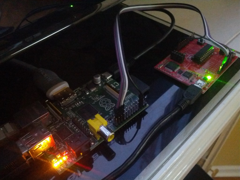
Wiring
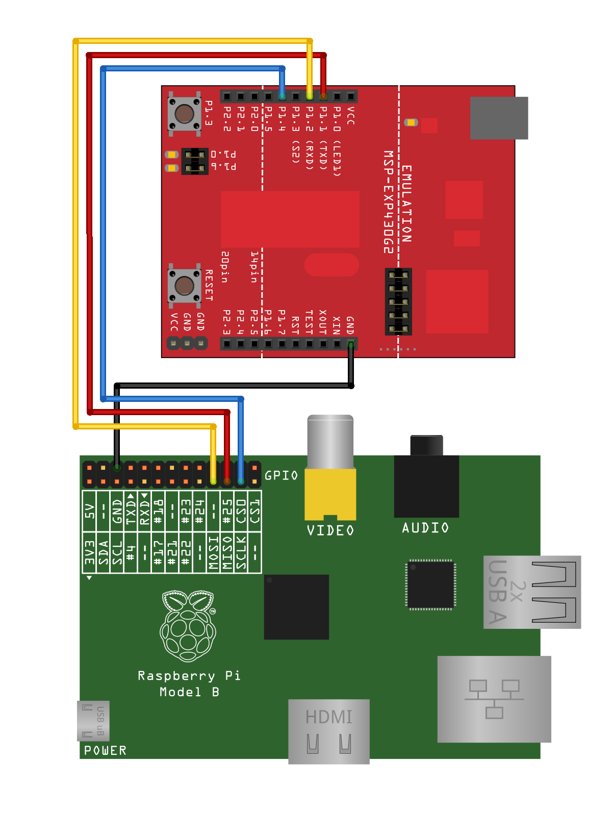
MSP430
Flash the below code to your MSP430 chip. Please see this tutorial for information on compiling and programming your MSP430.
MSP430 Code
Raspberry Pi
With your updated rasbian system you should have the drivers that you need. Now it’s time to load them.
modprobe spi_bcm2708
modprobe spidev
Check to be sure the modules loaded:
lsmod
Module Size Used by
spidev 5944 0
spi_bcm2708 5350 0
snd_bcm2835 21681 0
snd_pcm 81170 1 snd_bcm2835
snd_seq 59528 0
snd_timer 21602 2 snd_seq,snd_pcm
snd_seq_device 6924 1 snd_seq
snd 57427 5 snd_seq_device,snd_timer,snd_seq,snd_pcm,snd_bcm2835
snd_page_alloc 5343 1 snd_pcm
i2c_bcm2708 3822 0
Raspberry Pi Code
Save the below code as spidev_test.c on to your Raspberry Pi and compile it
gcc spidev_test.c -o spidev_test
Running
The MSP430 board LED1 will blink 3 times upon recognition of the SPI clock. After this initial sequence, when you SPI data “HELLO WORLD\n” to the MSP430 it will turn on the LED1 light. On your Raspberry Pi run the previously compiled program. The -s options sets the frequency of the clock when performing the SPI communication.
sudo ./spidev_test -s 120000
Again, a successful sending of “HELLO WORLD\n” will be denoted by LED1 lighting up on the MSP430 board.