topamax once a day

Arduino Poor Man’s Oscilloscope

This tutorial will show you how to use your Arduino as an oscilloscope.  We end the tutorial with a verification portion that uses the Arduino to generate a square wave, requiring a single wire.

lxardoscope

Lxardoscope is another Arduino + real-time graphing project that has the potential to turn an Arduino into an oscilloscope.  Unfortunately, I was unable to get any readings (the visual graph remained static).

Poor Man’s Oscilloscope

First, download processing.

http://processing.googlecode.com/files/processing-1.5.1-linux.tgz
gzip -d processing-1.5.1-linux.tgz
tar -xf processing-1.5.1-linux.tar

Desktop Application

Arduino uses a modified RXTXcomm.jar library.  This causes a problem when the processing project runs poor man’s oscilloscope and loads the RXTXcomm.jar library bundles with the processing project.  Instead, we wish for process to load the modified Arduino RXTXcomm.jar library.  To remedy this problem we simply replace processing RXTXcomm.jar with the Android specific RXTXcomm.jar.

rm processing-1.5.1/modes/java/libraries/serial/library/linux64/librxtxSerial.so
rm processing-1.5.1/modes/java/libraries/serial/library/RXTXcomm.jar
ln -s /usr/share/arduino/lib/RXTXcomm.jar processing-1.5.1/modes/java/libraries/serial/library/

Run processing

cd processing-1.5.1
./processing

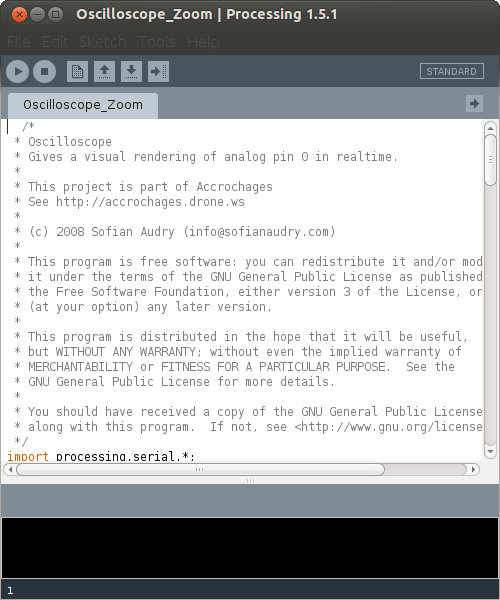
Running the processing command should result in a GUI application launching that looks a lot like the Arduino idea.  Download and open the below code in processing and click play.
  /*
 * Oscilloscope
 * Gives a visual rendering of analog pin 0 in realtime.
 * 
 * This project is part of Accrochages
 * See http://accrochages.drone.ws
 * 
 * (c) 2008 Sofian Audry (info@sofianaudry.com)
 *
 * This program is free software: you can redistribute it and/or modify
 * it under the terms of the GNU General Public License as published by
 * the Free Software Foundation, either version 3 of the License, or
 * (at your option) any later version.
 * 
 * This program is distributed in the hope that it will be useful,
 * but WITHOUT ANY WARRANTY; without even the implied warranty of
 * MERCHANTABILITY or FITNESS FOR A PARTICULAR PURPOSE.  See the
 * GNU General Public License for more details.
 * 
 * You should have received a copy of the GNU General Public License
 * along with this program.  If not, see <http://www.gnu.org/licenses/>.
 */ 
import processing.serial.*;

Serial port;  // Create object from Serial class
int val;      // Data received from the serial port
int[] values;
float zoom;

void setup() 
{
  size(1280, 480);
  // Open the port that the board is connected to and use the same speed (9600 bps)
  port = new Serial(this, Serial.list()[0], 9600);
  values = new int[width];
  zoom = 1.0f;
  smooth();
}

int getY(int val) {
  return (int)(height - val / 1023.0f * (height - 1));
}

int getValue() {
  int value = -1;
  while (port.available() >= 3) {
    if (port.read() == 0xff) {
      value = (port.read() << 8) | (port.read());
    }
  }
  return value;
}

void pushValue(int value) {
  for (int i=0; i<width-1; i++)
    values[i] = values[i+1];
  values[width-1] = value;
}

void drawLines() {
  stroke(255);
  
  int displayWidth = (int) (width / zoom);
  
  int k = values.length - displayWidth;
  
  int x0 = 0;
  int y0 = getY(values[k]);
  for (int i=1; i<displayWidth; i++) {
    k++;
    int x1 = (int) (i * (width-1) / (displayWidth-1));
    int y1 = getY(values[k]);
    line(x0, y0, x1, y1);
    x0 = x1;
    y0 = y1;
  }
}

void drawGrid() {
  stroke(255, 0, 0);
  line(0, height/2, width, height/2);
}

void keyReleased() {
  switch (key) {
    case '+':
      zoom *= 2.0f;
      println(zoom);
      if ( (int) (width / zoom) <= 1 )
        zoom /= 2.0f;
      break;
    case '-':
      zoom /= 2.0f;
      if (zoom < 1.0f)
        zoom *= 2.0f;
      break;
  }
}

void draw()
{
  background(0);
  drawGrid();
  val = getValue();
  if (val != -1) {
    pushValue(val);
  }
  drawLines();
}

Arduino Code

Arduinoscope has a simple arduino component to poll and forward analog 0 to the desktop via the serial connection.  Save the below code and flash it to your Arduino.

#define ANALOG_IN 0

void setup() {
  Serial.begin(9600); 
  //Serial.begin(115200); 
}

void loop() {
  int val = analogRead(ANALOG_IN);                                              
  Serial.write( 0xff );                                                         
  Serial.write( (val >> 8) & 0xff );                                            
  Serial.write( val & 0xff );
}


Verifying the Oscilloscope

To test the oscilloscope we will generate data using the Arduino and feed it in to the analog A0 port to be viewed on our Desktop.  Flash the code below to your Arduino.

// The Arduino code.                                                            
                                                                                
#define ANALOG_IN 0                                                             
int outPin=13;                                                                  
int outPinState = LOW;                                                          
int count = 1;                                                                  
int every = 10000;                                                              
                                                                                
void setup() {                                                                  
  //Serial.begin(9600);                                                         
  Serial.begin(115200);                                                         
}                                                                               
                                                                                
void loop() {                                                                   
  int val = analogRead(ANALOG_IN);                                              
  Serial.write( 0xff );                                                         
  Serial.write( (val >> 8) & 0xff );                                            
  Serial.write( val & 0xff );                                                   
                                                                                
  /* Generate signal to test oscilloscope */                                    
  if ((count % every) == 0) {                                                   
    if (outPinState == LOW) {                                                   
      outPinState = HIGH;                                                       
    } else {                                                                    
      outPinState = LOW;                                                        
    }                                                                           
    digitalWrite(outPin, outPinState);                                          
    count = 0;                                                                  
  }                                                                             
  count++;                                                                      
}

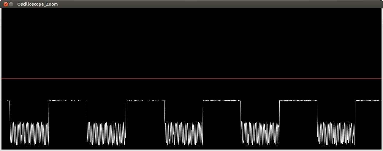
Connect pin digital pin 13 on the Arduino to analog pin A0.  The above code will turn on and off the digital pin to produce a square wave.
Extras

  • You can alter the baud rate from 9600 to 115200 in the arduino code as well as the processing code.
  • Plus sign zooms in (shift and =) while – zooms out (just -, no shift)
  • PWM at a normal 50 HZ is easily observable
  • Raspberry Pi pin 18 can generate PWM and the arduino can be used to test it.
  • An idle capture looks like:
  • Arduino lover

    if you like everything related to micro-controllers visit my blog:

    All about Embedded Systems

  • Nanu

    The Arduino-part says:
    12: error: ‘gt’ was not declared in this scope

    • meyers

      Nanu, somehow some characters got converted to html-safe representation. I updated the gist but it isn’t reflecting that update here. Click “This Gist” to see the updated version.

  • C.A Majdi

    Hello, i try to make this work, but i fail on Processing programming. How to modify RXTXcomm.jar as explain above?

  • superzed

    It worked for me. But when the baud rate is 9600, it was only showing step signal not pulse/square signal. My arduino is Arduino mega atmega1280.

  • Well done. You might want to have a look at a project of mine that is quite similar to this one. http://sebastiannilsson.com/en/k/projekt/realtime-plotter/

  • Pingback: Arduino Netduino: Oscilloscope and Logic Analyzer - Secret Microsoft Communications - Site Home - MSDN Blogs()

  • Humannoise

    Hi, i got the following error when i play the processing code:

    java.lang.UnsatisfiedLinkError: no rxtxSerial in java.library.path thrown while loading gnu.io.RXTXCommDriver