Android + IOIO + Software Joystick Servos
Android and IOIO powered pan and tilt servo bracket controlled by software joystick.
For additional background information on interfacing Android with IOIO, check out my other introductory tutorials:
Android + IOIO + Simple Digital Output
Android + IOIO + Simple Digital Input
Android + IOIO + Simple Analog Output
Android + IOIO + Simple Analog Input
Background on Android development, IOIO, and electronics:
IOIO for Android Beginners Guide
Hardware
Parts needed:
-
Android Device (1.6+, 2.1 for Bluetooth)
-
IOIO (available at Sparkfun)
-
2x Hobby servo
-
2x 10k ohm resistors
-
Breadboard
-
Power supply
-
Hook-up wire
Assembly
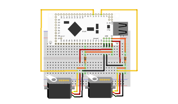
Connect the red, power lines of the servos to +5v, the black ground lines to GND, and the yellow signal lines to the desired output pins, number 3 and 6 in the example below. Other pins can be used as long as they support peripheral output (for PWM, marked with the letter ‘p’ on the back of the IOIO) AND are 5V tolerant (marked with a black circle around the pin). This leaves pins 3-7, and 10-14 as the only potentials. Also, connect the same signal lines to +5V, with a 10k ohm resistor in series. This allows use of the pins in 5V open drain mode, required since the IOIO operates with 3.3V. Here is a diagram of the completed circuit (created with Fritzing):
Software
Get the source
With the circuit assembled, the next step is to get the demo application on the Android device. You can either download the pre-built .apk or checkout the source from Github:
git clone git://github.com/mitchtech/android_ioio_software_joystick.git
If you are building from source, you will also need to import the IOIO Library project, and optionally the IOIO Bluetooth library projects, both available here:
git clone git://github.com/ytai/ioio.git
Install, connect, profit!
Finally, upload the app to the Android device (or browse to this page on the device and download the apk above). Connect the device to the IOIO, and start up the app.