Android + IOIO + Garage Door
Control your garage door with Android and IOIO.
For additional background information on interfacing Android with IOIO, check out my other introductory tutorials:
Android + IOIO + Simple Digital Output
Android + IOIO + Simple Digital Input
Android + IOIO + Simple Analog Output
Android + IOIO + Simple Analog Input
Background on Android development, IOIO, and electronics:
IOIO for Android Beginners Guide
Hardware
Parts needed:
-
Android Device (1.6+, 2.1 for Bluetooth)
-
IOIO (available at Sparkfun)
-
Hackable garage door remote
-
2N3904 transistor
-
10k ohm resistor
-
5V DC Relay
-
Breadboard
-
Power supply
-
Hook-up wire
Assembly
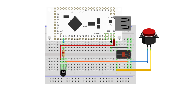
First, remove the outer plastic case from the garage door controller. Locate the two sides of the button that are connected when depressed. Solder a lead to both sides, and connect these leads to the two sides of the switch terminal of the relay. Now the relay is ready to ‘press’ the button with the coil is activated.
Then connect the base of the transistor to the desired IOIO pin with a 10k ohm resistor in series. Connect the collector to +5v and the emitter to the one side of the relay coil. Finally, connect the opposite side of the relay coil to GND. Here is a diagram of the completed circuit (created with Fritzing). Note: the button on the right side represents the remote garage door controller:
Software
Get the source
With the circuit assembled, the next step is to get the demo application on the Android device. You can either download the pre-built .apk or checkout the source from Github:
git clone git://github.com/mitchtech/android_ioio_garage_door.git
If you are building from source, you will also need to import the IOIO Library project, and optionally the IOIO Bluetooth library projects, both available here:
git clone git://github.com/ytai/ioio.git
Install, connect, profit!
Finally, upload the app to the Android device (or browse to this page on the device and download the apk above). Connect the device to the IOIO, and start up the app.