Raspberry Pi + Arduino + SPI
This tutorial will show you how to communicate from your raspberry pi to your arduino using 3-wire SPI.
Requirements
-
1 Raspberry pi (running Raspbian)
-
1 Arduino
-
4 wires
Your raspberry pi should be running the newest version of Raspbian. To ensure your system is up-to-date please download and run rpi-update.
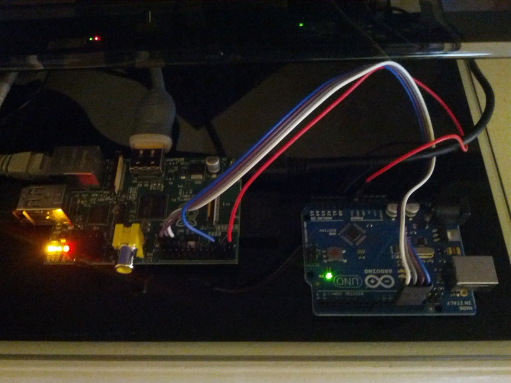
Wiring
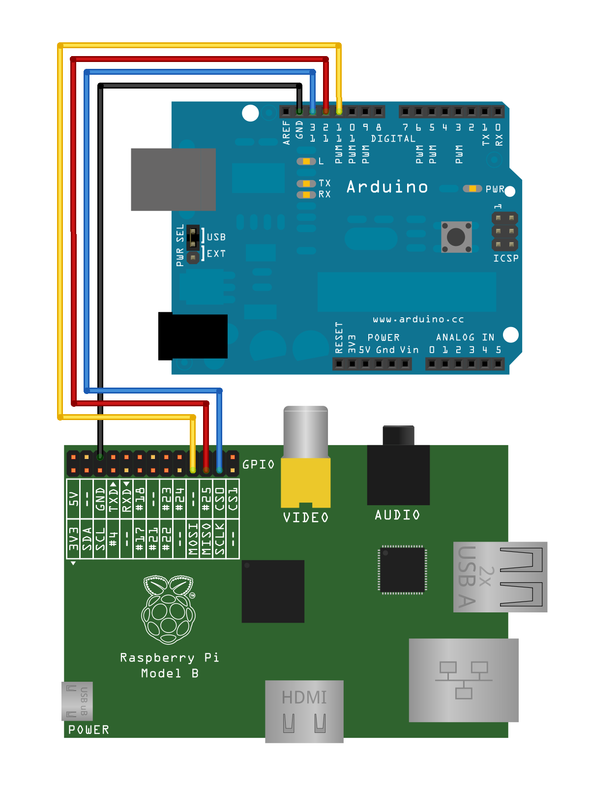
Arduino
Open your Arduino ide and flash the below code to your Arduino.
Arduino code
Raspberry Pi
With your updated rasbian system you should have the drivers that you need. Now it’s time to load them.
modprobe spi_bcm2708
modprobe spidev
Check to be sure the modules loaded:
lsmod
Module Size Used by
spidev 5944 0
spi_bcm2708 5350 0
snd_bcm2835 21681 0
snd_pcm 81170 1 snd_bcm2835
snd_seq 59528 0
snd_timer 21602 2 snd_seq,snd_pcm
snd_seq_device 6924 1 snd_seq
snd 57427 5 snd_seq_device,snd_timer,snd_seq,snd_pcm,snd_bcm2835
snd_page_alloc 5343 1 snd_pcm
i2c_bcm2708 3822 0
Raspberry Pi Code
Save the below code as spidev_test.c on to your Raspberry Pi and compile it
gcc spidev_test.c -o spidev_test
Running
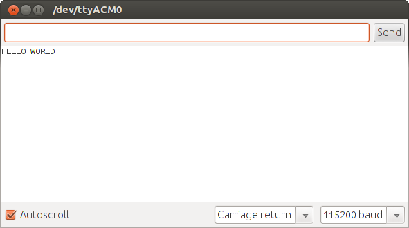
Plug your Arduino to your desktop via the serial cable. Open the arduino Serial Monitor and set the bitrate to 115200. Now, on the Raspberry Pi, run the compiled code
sudo ./spidev_test
You should see HELLO WORLD print in the Arduino IDE Serial Monitor.
Debugging
- Make sure that your kernel has the required drivers (spi-bcm2708.ko and spidev.ko)
pi@raspberrypi ~/spi $ ls -al /lib/modules/`uname -r`/kernel/drivers/spi/
total 64
drwxrwxr-x 2 pi pi 4096 Aug 10 10:53 .
drwxrwxr-x 23 pi pi 4096 Aug 10 10:53 ..
-rw-rw-r-- 1 pi pi 14428 Aug 10 10:53 spi-bcm2708.ko
-rw-rw-r-- 1 pi pi 10852 Aug 10 10:53 spi-bitbang.ko
-rw-rw-r-- 1 pi pi 15803 Aug 10 10:53 spidev.ko
-rw-rw-r-- 1 pi pi 10693 Aug 10 10:53 spi-gpio.ko
Thanks to Nick Gammon for the SPI slave code.
Thanks to Anton Vorontsov for the kernel Documentation spidev_test.c example code.