Arduino Poor Man's Oscilloscope
This tutorial will show you how to use your Arduino as an oscilloscope. We end the tutorial with a verification portion that uses the Arduino to generate a square wave, requiring a single wire.
lxardoscope
Lxardoscope is another Arduino + real-time graphing project that has the potential to turn an Arduino into an oscilloscope. Unfortunately, I was unable to get any readings (the visual graph remained static).
Poor Man’s Oscilloscope
First, download processing.
http://processing.googlecode.com/files/processing-1.5.1-linux.tgz
gzip -d processing-1.5.1-linux.tgz
tar -xf processing-1.5.1-linux.tar
Desktop Application
Arduino uses a modified RXTXcomm.jar library. This causes a problem when the processing project runs poor man’s oscilloscope and loads the RXTXcomm.jar library bundles with the processing project. Instead, we wish for process to load the modified Arduino RXTXcomm.jar library. To remedy this problem we simply replace processing RXTXcomm.jar with the Android specific RXTXcomm.jar.
rm processing-1.5.1/modes/java/libraries/serial/library/linux64/librxtxSerial.so
rm processing-1.5.1/modes/java/libraries/serial/library/RXTXcomm.jar
ln -s /usr/share/arduino/lib/RXTXcomm.jar processing-1.5.1/modes/java/libraries/serial/library/
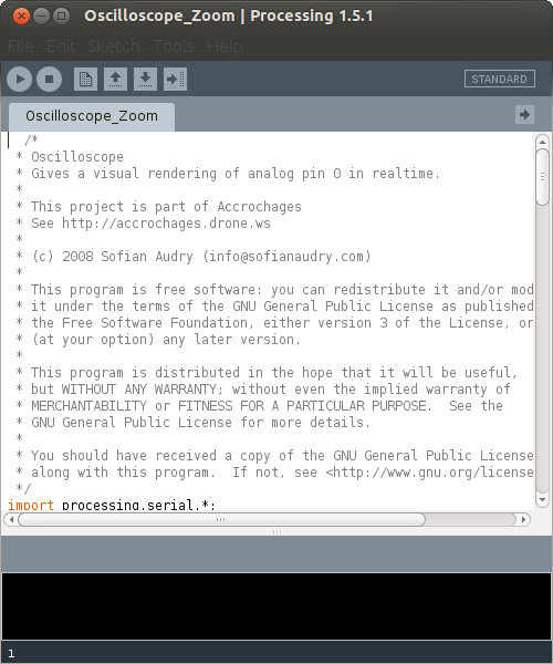
Run processing
cd processing-1.5.1
./processing
Running the processing command should result in a GUI application launching that looks a lot like the Arduino idea. Download and open the below code in processing and click play.
Arduino Code
Arduinoscope has a simple arduino component to poll and forward analog 0 to the desktop via the serial connection. Save the below code and flash it to your Arduino.

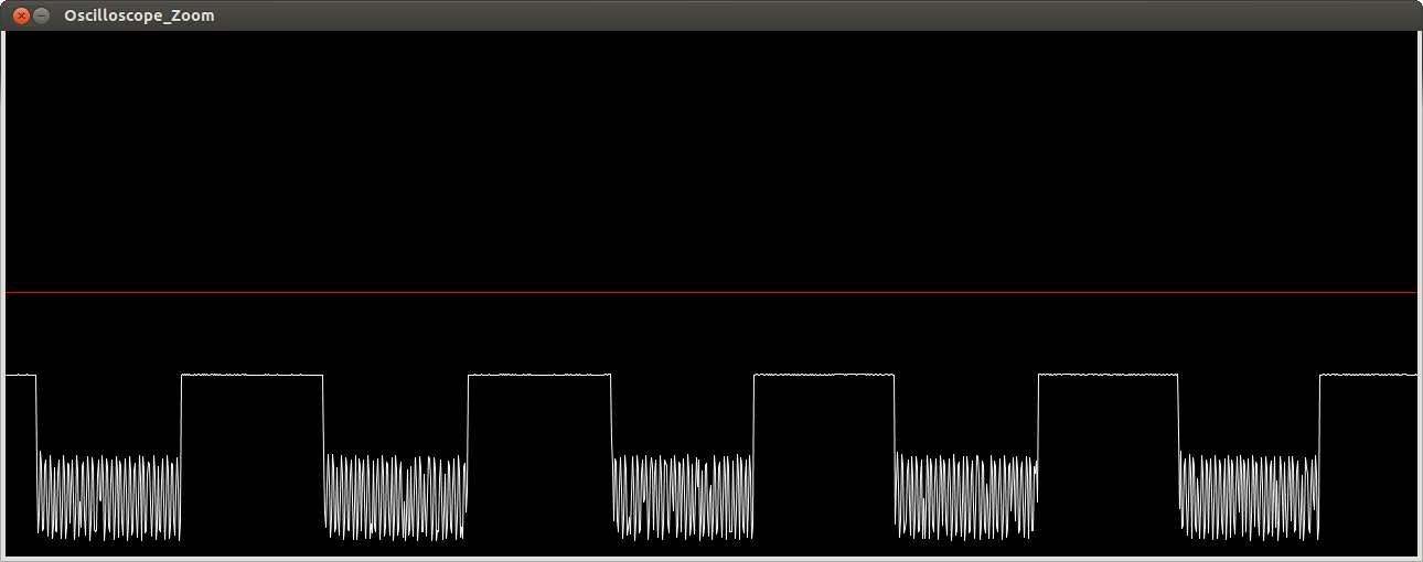
Verifying the Oscilloscope
To test the oscilloscope we will generate data using the Arduino and feed it in to the analog A0 port to be viewed on our Desktop. Flash the code below to your Arduino.
Connect pin digital pin 13 on the Arduino to analog pin A0. The above code will turn on and off the digital pin to produce a square wave.
Extras
-
You can alter the baud rate from 9600 to 115200 in the arduino code as well as the processing code.
-
Plus sign zooms in (shift and =) while - zooms out (just -, no shift)
-
PWM at a normal 50 HZ is easily observable
-
Raspberry Pi pin 18 can generate PWM and the arduino can be used to test it.
-
An idle capture looks like:
