Android + IOIO + Simple Analog Output
Simplest possible analog output with Android and IOIO. This article will discuss the bare minimal requirements for development of an Android USB (or Bluetooth) analog output device, a controllable RGB LED.
The goal is to demonstrate the easiest possible use of the technology. For additional background information on Android development, IOIO, and electronics, check out these links:
IOIO for Android Beginners Guide
Hardware
Parts needed:
-
Android Device (1.6+, 2.1 for Bluetooth)
-
IOIO (available at Sparkfun)
-
RGB LED
-
3x 330 ohms resistors
-
Breadboard
-
Power supply
-
Hook-up wire
Assembly
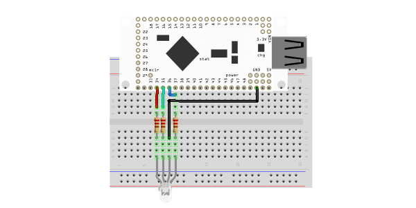
The RGB LED has four leads: the three short ones are anodes that correspond to each of the three colors (red, green, and blue) and the fourth, longer lead is the common cathode. Connect the 330 ohm resistors in series with the anodes of the LED and the common cathode to ground. The example uses pins 34, 35, and 36, but can be used with other pins that support PWM output (pins 3-7, 10-14, 27-32, 34-40, 45-48… marked with the letter ‘p’ on the back of the IOIO). The resistors, in this case, are being used to prevent current overdraw to the LED. Here is a diagram of the completed circuit (created with Fritzing):
Software
Get the source
With the circuit assembled, the next step is to get the demo application on the Android device. You can either download the pre-built .apk or checkout the source from Github:
git clone git://github.com/mitchtech/android_ioio_simple_analog_output.git
If you are building from source, you will also need to import the IOIO Library project, and optionally the IOIO Bluetooth library projects, both available here:
git clone git://github.com/ytai/ioio.git
Install, connect, profit!
Finally, upload the app to the Android device (or browse to this page on the device and download the apk above). Connect the device to the IOIO, and start up the app.