Android + IOIO + Seven Segment LED
Basic control of a seven segment LED display with IOIO and Android.
For additional background information on interfacing Android with IOIO, check out my other introductory tutorials:
Android + IOIO + Simple Digital Output
Android + IOIO + Simple Digital Input
Android + IOIO + Simple Analog Output
Android + IOIO + Simple Analog Input
Background on Android development, IOIO, and electronics:
IOIO for Android Beginners Guide
Hardware
Parts needed:
-
Android Device (1.6+, 2.1 for Bluetooth)
-
IOIO (available at Sparkfun)
-
Seven segment LED display
-
330k ohm resistors
-
Breadboard
-
Power supply
-
Hook-up wire
Assembly
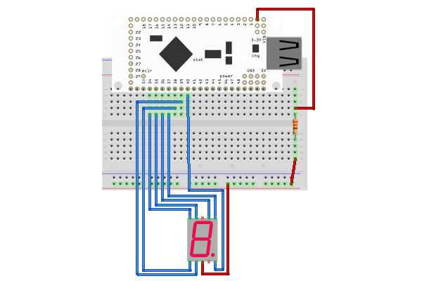
The LED display is common anode with pins 3 and 8 (top center and bottom center) to ground with a current limiting 330 ohm resistor in series. Connect the seven segment pins as shown below to IOIO pins 34 -40. The code can be modified for use with any other IO pins (all IOIO pins are GPIO pins). Here is a diagram of the completed circuit (created with Fritzing):
Software
Get the source
With the circuit assembled, the next step is to get the demo application on the Android device. You can either download the pre-built .apk or checkout the source from Github:
git clone git://github.com/mitchtech/android_ioio_seven_segment_led.git
If you are building from source, you will also need to import the IOIO Library project, and optionally the IOIO Bluetooth library projects, both available here:
git clone git://github.com/ytai/ioio.git
Install, connect, profit!
Finally, upload the app to the Android device (or browse to this page on the device and download the apk above). Connect the device to the IOIO, and start up the app.