Android + Arduino + USB Host + Simple Analog Input
Simplest possible analog input with the ADK. This article will discuss the bare minimal requirements for development of a basic USB input accessory. The goal is to demonstrate the easiest possible use of the technology. For additional background information on Android development, Arduino, and MicroBridge, check out these links:
Getting Started
First, make sure you have setup the development environments for Arduino and Android:
Hardware
Parts needed:
-
Android Device (1.6+)
-
Photocell
-
10K ohm resistor
-
Hook-up wire
-
Android ADK Board*
-
– OR –
-
Arduino compatible and USB Host shield
*Supported boards include:
Google ADK board, Freeduino ADK board , Seeed Studio ADK board, and DIY Drones ADK board
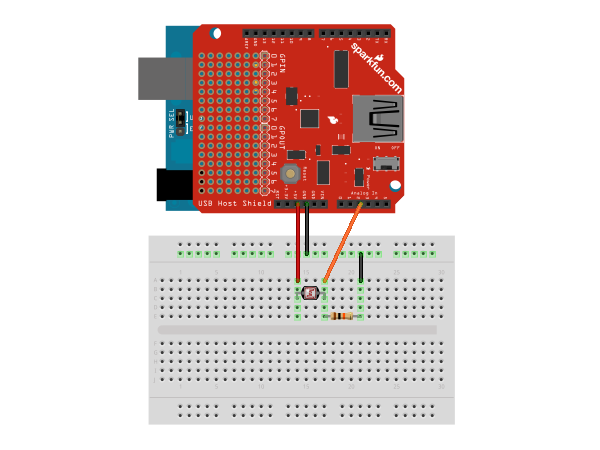
Assembly
Connect one of the photocell leads to 5v and the other to analog input pin A0. Also connect the same lead through a 10K resistor to ground. In hardware, this concept is known as a voltage divider. Here is a diagram of the completed circuit (created with Fritzing):
Software
Arduino Firmware
Next, upload the Arduino sketch to the microcontroller. The sketch uses the Microbridgeimplementation by Niels Brouwers. Microbridge uses Android Debug Bridge (ABD) forwarding over TCP, rather than the Google Android ADK. You can checkout the source for the Arduino sketch from Github, or just copy and paste the following into the Arduino IDE.
Android App
The next step is to install the Android Demo application onto the device. You can either download the pre-built .apk or checkout the source from Github:
git clone git://github.com/mitchtech/android_adb_simple_analog_input.git
Finally upload the app to the device (or browse to this page on the device and download the apk above). Connect the Android device to the USB Host board/shield, and start up the app.