Android + Arduino + USB Host + D-Pad
A simple controller for use as an Android directional pad input accessory. The Arduino based device uses four momentary push buttons to sense digital inputs for up, down, left, and right.
For additional background information on interfacing Android with the real world, check out my other introductory tutorials:
Hardware
Parts needed:
-
Android Device (1.6+)
-
4x Push buttons
-
Breadboard
-
Power supply
-
Hook-up wire
-
Android ADK Board*
-
– OR –
-
Arduino compatible and USB Host shield
*Supported boards include:
Google ADK board, Freeduino ADK board , Seeed Studio ADK board, and DIY Drones ADK board
Assembly
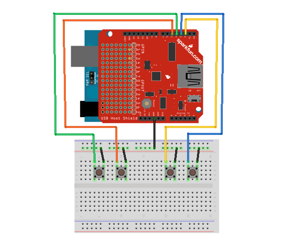
Connect one side of each button to ground and the other side to the desired digital input pins. Here is a diagram of the completed circuit (created with Fritzing):
Software
Arduino Firmware
Next, upload the Arduino sketch to the microcontroller. The sketch uses the Microbridge implementation by Niels Brouwers. Microbridge uses Android Debug Bridge (ABD) forwarding over TCP, rather than the official Google Android ADK. You can checkout the source for the Arduino sketch from Github, or just copy and paste the following into the Arduino IDE.
Android App
Finally, install the Android Demo application onto the device. You can either download the pre-built .apk or checkout the source from Github:
git clone git://github.com/mitchtech/android_adb_d_pad.git
Finally upload the app to the device (or browse to this page on the the device and download the apk above). Connect the Android device to the USB Host board/shield, and start up the app.